Introduction to the RGB to HDMI Schematic Design for TI AM62x
The TI AM62x is a high-performance processor developed by Texas Instruments, widely used in industrial and embedded systems. It supports high-speed RGB output with resolutions up to 1920x1080P. However, RGB transmission is limited in distance and prone to interference in industrial environments. To address this, converting RGB signals to HDMI provides a more stable solution suitable for modern HD display devices. This article introduces the core principles and key aspects of the RGB-to-HDMI schematic design based on the TI AM62x.
1. Working Principle of RGB to HDMI Conversion
The RGB-to-HDMI conversion involves transforming parallel RGB signals from the processor into HDMI-compatible TMDS (Transition-Minimized Differential Signaling) signals. The basic process is as follows:
●RGB Signal Output: The AM62x outputs video data via the RGB interface, including RGB data (R[7:0], G[7:0], B[7:0]), timing signals (HSYNC, VSYNC), and a pixel clock (PCLK).
●Timing Signal Processing: The RGB timing must comply with HDMI standards, configured via pins or registers for parameters such as resolution and refresh rate.
●Signal Conversion: An RGB-to-HDMI converter chip (e.g., Sil9022) is used to transform RGB data and timing signals into HDMI output.
2. Core Design Modules
2.1 Processor RGB Interface Pin Connections
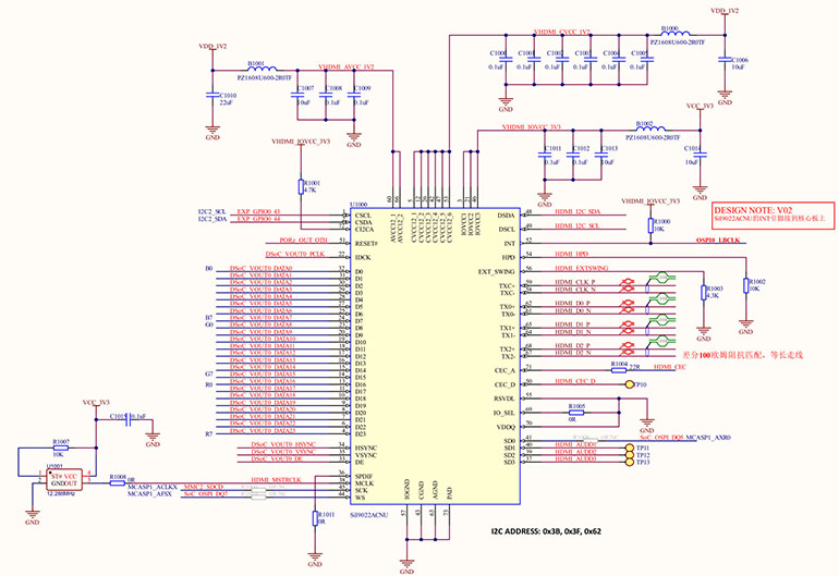
The AM62x RGB interface includes 24-bit data lines (R[7:0], G[7:0], B[7:0]), clock signals (PCLK), and control signals (HSYNC, VSYNC, DE). It is essential to ensure the data width and resolution of the chip meet design requirements. PCB layout should maintain data line length consistency to reduce signal delay and interference.

Figure 1 RGB to HDMI Schematic Diagram
2.2 RGB to HDMI Chip Selection
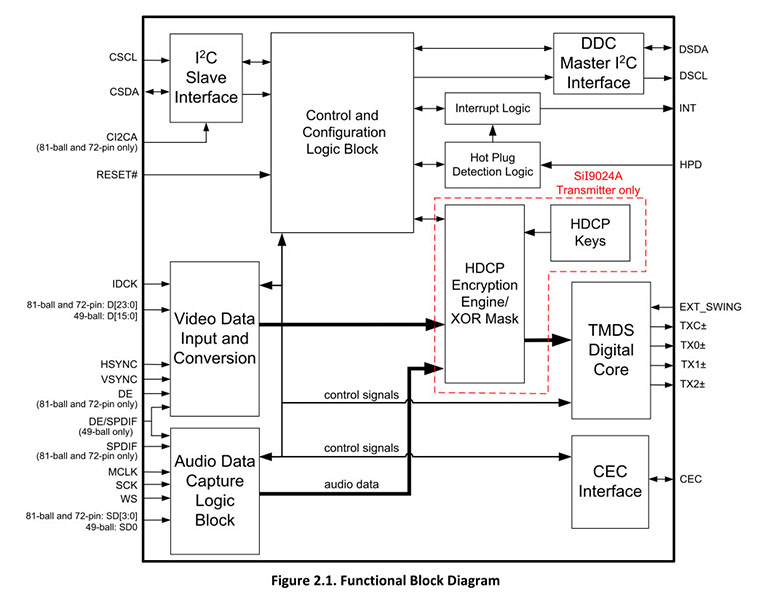
Choose an RGB-to-HDMI converter chip that supports the target resolution and refresh rate, such as the Sil9022, which supports 1080p@60Hz. The chip must precisely match the processor’s clock and synchronization signals to avoid image jitter or frame loss.

Figure 2 sil9022 block diagram
2.3 I2C Configuration Interface
The RGB-to-HDMI chip requires configuration via I2C to set parameters like resolution and clock frequency. The AM62x has a built-in I2C interface that communicates directly with the converter chip. Pull-up resistors (typically 4.7kΩ) are necessary for the I2C bus in the schematic.
2.4 Power Supply Design
Ensure the RGB-to-HDMI chip receives the correct supply voltage (e.g., 3.3V or 1.8V). Decoupling capacitors (e.g., 0.1µF and 10µF) should be added to reduce power noise interference.
2.5 HDMI Interface Design
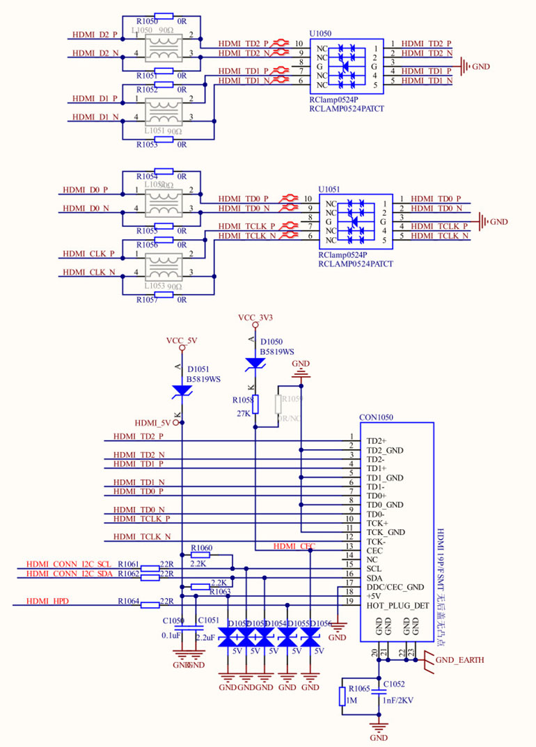
The TMDS differential signal pairs in the HDMI interface require precise impedance matching (usually 100Ω). Differential signal pairs should maintain equal lengths and be routed close to the ground plane to minimize electromagnetic interference. ESD protection circuits are recommended to prevent damage to the chip and HDMI interface.

Figure 3 HDMI interface schematic
3. Schematic Design Considerations
3.1 Signal Integrity
Ensure impedance control for RGB signal lines and TMDS differential signal pairs to prevent reflection or distortion. In PCB design, differential signal length mismatches should be less than 0.15mm.
3.2 Power Management
Each power pin should be individually decoupled to minimize high-frequency noise. For HDMI output, an additional 5V power supply is required for external devices (via HDMI VCC).
3.3 Clock Synchronization
PCLK serves as the reference clock for signal transmission. Its frequency must remain stable, and a crystal oscillator is recommended for precise clock sourcing.
3.4 Test Points
Add test points for critical signals (e.g., PCLK, HSYNC, VSYNC, TMDS differential signals) to facilitate debugging and signal measurement.
4. Conclusion
RGB-to-HDMI schematic design based on TI AM62x requires a comprehensive approach, covering processor signal characteristics, converter chip selection, and PCB layout. Through well-thought-out schematic design and hardware tuning, high-quality HDMI video output can be achieved, offering a reliable solution for modern display applications.
As a TI third-party partner, we can provide support in circuit design. We recommend using the WTC-AM62XXS SOM developed by Weathink for this application.
We hope this article serves as a useful reference for your design. Feel free to contact us for further design support or case studies!


