Schematic Design for Debug UART to USB on Rockchip RK3568
In embedded system development, the debug UART is a crucial tool for engineers to conduct debugging and problem identification. The RK3568, a high-performance processor widely used in industrial control and embedded devices, requires a robust UART-to-USB design to facilitate communication. This design enables developers to conveniently connect the device to a PC via a USB interface, ensuring high-speed and stable communication during debugging. This article details the schematic design of the UART-to-USB converter for the RK3568 and highlights key considerations.
1. Basic Principles of UART-to-USB Conversion
The core of UART-to-USB conversion involves using a USB-to-serial chip (such as CH340, CP2102, or FT232) to convert the UART signals output by the RK3568 into USB signals for connection to PCs or other terminals. The workflow is as follows:
●UART Signal Output: The RK3568 debug UART outputs standard UART signals via TX (transmit), RX (receive), and GND pins.
●Signal Conversion: A USB-to-serial chip converts UART signals into USB protocol signals for high-speed transmission.
●USB Communication: The PC receives these signals through the USB interface and, using appropriate drivers, maps them to a virtual COM port for communication with the embedded device.
2. Schematic Design
2.1 UART Pin Connections
The RK3568 typically uses UART0 or UART1 as the default debug UART. The pin definitions are:
●TXD: UART transmit data pin
●RXD: UART receive data pin
●GND: Ground
Ensure that the RK3568’s RXD connects to the USB-to-serial chip's TXD, and the RK3568's TXD connects to the chip's RXD, sharing a common ground for proper signal transmission.
2.2 USB-to-Serial Chip Selection
Commonly used USB-to-serial chips include:
●CH340: Cost-effective and widely used, but requires a driver installation on the PC.
●CP2102: Stable performance with a built-in oscillator and broad voltage range support.
●FT232: Feature-rich and supports various operating systems but is relatively expensive.
Considering the RK3568’s UART baud rate of 1.5 Mbps, which exceeds the typical rates for debug UARTs, this article uses CH340T as an example. CH340T uses an external crystal oscillator for precision, maintaining a baud rate error of less than 0.3%, making it suitable for rates above 1 Mbps.
Connection Details:
●UART Interface: CH340T’s RXD connects to RK3568’s TXD, and CH340T’s TXD connects to RK3568’s RXD.
●USB Interface: CH340T’s USB D+ and D- connect to the USB port via a differential circuit.
●Power Supply: CH340T typically derives 5V from the USB interface and uses its internal LDO to provide 3.3V for internal logic.
2.3 Signal Protection and Filtering
ESD Protection: Add ESD protection components (e.g., TVS diodes) to USB D+ and D- pins to prevent static electricity damage to the chip.
Decoupling Capacitors: Place decoupling capacitors (e.g., 0.1 µF and 4.7 µF) between the power pins (VCC and GND) to reduce power noise interference.
2.4 Crystal Oscillator Circuit
The CH340T requires an external 12 MHz crystal oscillator as its clock source. Connect load capacitors (typically 18 pF) to both ends of the crystal to ensure proper operation.
2.5 USB Interface Design
USB Connector Type: Use a USB Type-C interface based on design requirements.
Impedance Matching: Ensure the differential pair (USB D+ and D-) impedance is designed to 90Ω ±10% to maintain signal integrity.
2.6 Level Shifting
To prevent leakage, convert the RK3568’s UART voltage level via MOSFETs or diodes before feeding it to the CH340T. This ensures no residual voltage is applied to the RK3568 UART pins when the Type-C USB is connected and powered on.

Figure 1 CH340T connected to RK3568 debug serial port schematic design
3. Debugging and Validation
After completing the hardware design, validate the UART-to-USB functionality as follows:
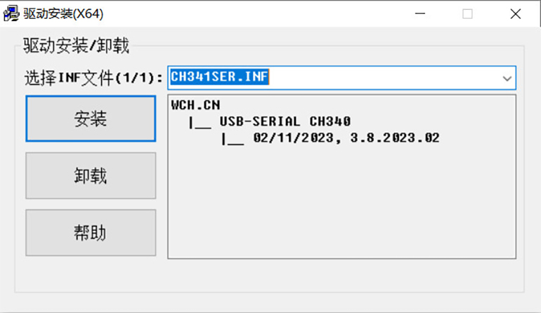
3.1 Driver Installation
Ensure the PC has the appropriate USB-to-serial chip driver (e.g., CH340T driver). Once installed, the virtual COM port (e.g., COM3) should appear in the device manager.

Figure 2 CH340T driver installation
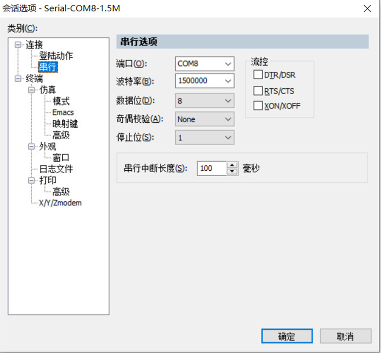
3.2 Serial Communication Testing
Use a serial debugging tool (e.g., SecureCRT) to connect to the virtual COM port. Configure the baud rate (1500000 bps), data bits, stop bits, and parity settings to match the RK3568.

Figure 3 SecureCRT settings
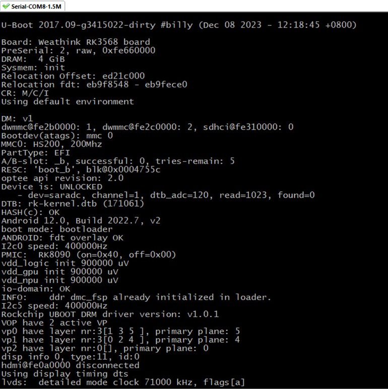
3.3 Functionality Validation
Output debug information (e.g., boot logs) from the RK3568 and verify that the serial debugging tool on the PC can receive the output correctly.

Figure 4 Serial port debugging output
4. Design Considerations
Power Voltage Matching: Ensure the UART voltage levels of the RK3568 and the USB-to-serial chip are compatible (typically 3.3V). If not, use a level-shifting circuit.
Signal Routing: Keep TXD and RXD signal lines on the PCB short and straight to minimize crosstalk and signal delay. Ensure the USB D+ and D- lines are equal in length and routed close to the ground plane.
Driver Compatibility: Prefer USB-to-serial chips that support multiple platforms to improve software compatibility.
5. Conclusion
The UART-to-USB design for Rockchip RK3568 enables stable and reliable serial debugging through proper component selection and schematic optimization. This article uses the CH340T as an example to elaborate on the design process and considerations, offering practical guidance for engineers. With this design, developers can efficiently debug and develop embedded systems.
The schematic provided is implemented in the WTB-RK3568S Single Board Computers designed by Weathink. As a professional Single Board Computers design company, Weathink integrates various application requirements into its designs, which have been tested in production. For any issues, feel free to contact Weathink.


