Features
CPU: Renesas G2L
Architecture: Dual Cortex A55
Main frequency: 1.2GHz
Memory: 1GB/2GB DDR4 Industrial Grade
Flash: 8Gbyte EMMC
Operate system: linux
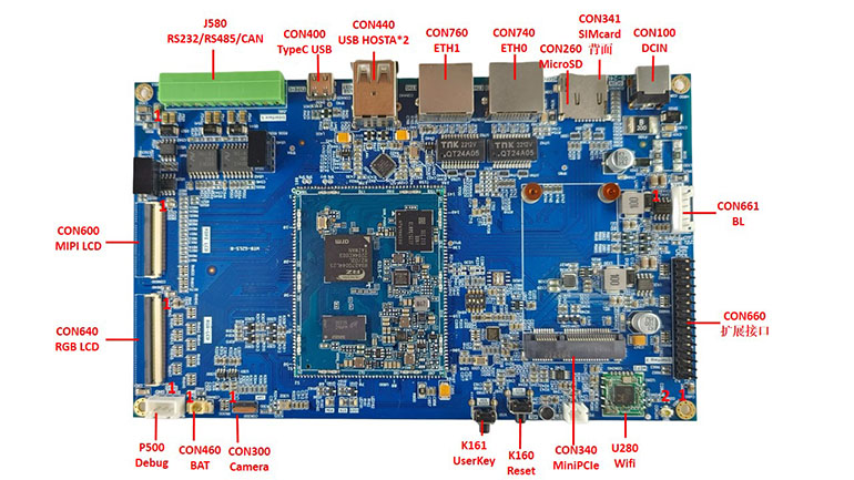
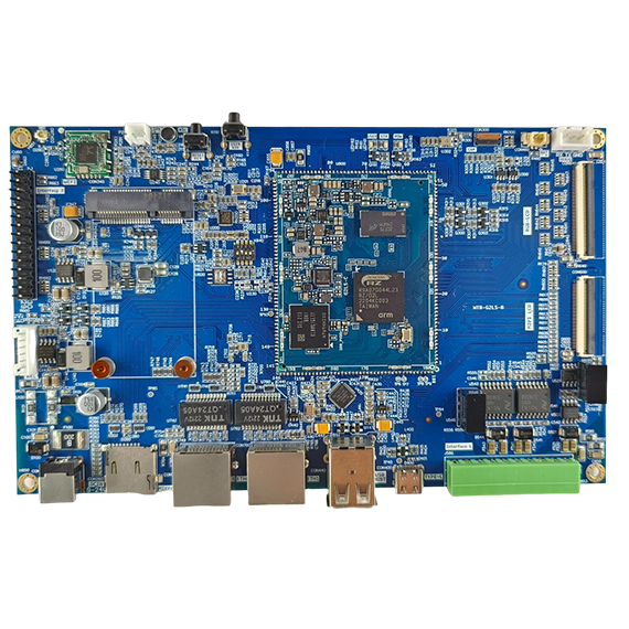
G2L Industrial Control Board is an industrial Control board designed based on G2L Core Board. The ARM Cortex-A55 architecture has a running frequency of 1 2GHz. All components of Core Board are industrial grade, and the most wide range of the entire board can reach -40 ° C ~+85 ° C. The DDR4 memory of the plate 2GBYTE is stored, and the storage uses an 8Gbyte EMMC storage chip (1G capacity optional). The rectification performance is stable and the resources are rich.
interface | describe |
CPU | LCD screen |
Operating temperature | -40℃~+85℃ |
Architecture | ARMv8 Cortex-A55 |
Main frequency | 1.2GHZ |
Memory | 2GB DDR4 |
ROM | 8GB eMMC |
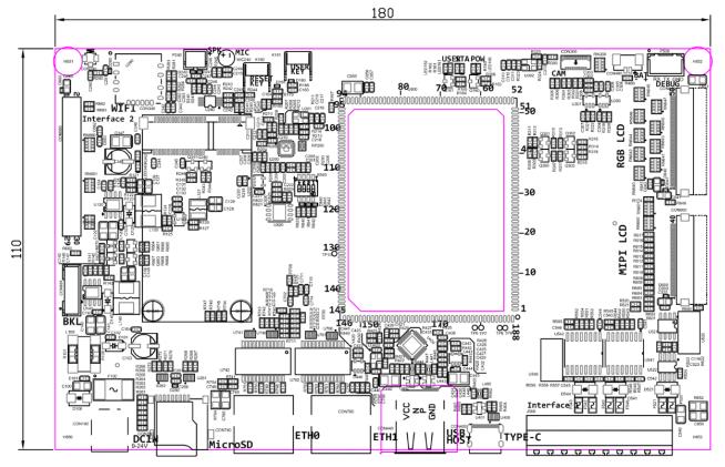
Size | 180mm*110mm |
Relative humidity | 10%~90%(No exposure) |
Operating Voltage | 9~24V DC |
Mechanical Dimensions:

Product function box diagram:

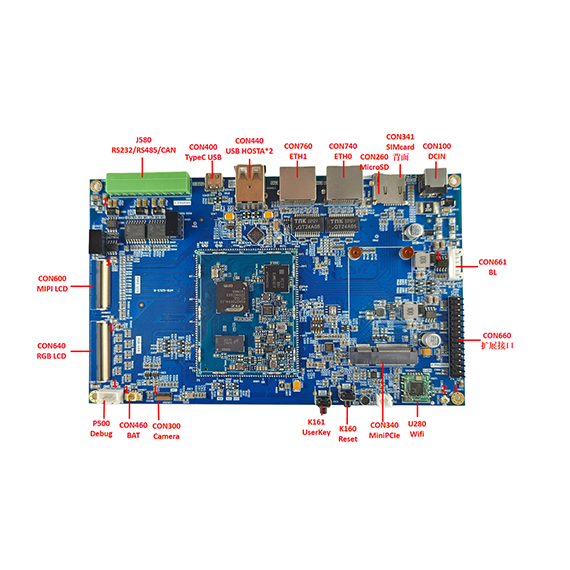
Interface Description

2.5.1 Con660 expansion interface
Pins | Pins | All function or introduction |
1 | 5V_OUT | 5V power output output |
2 | IN2_P | Microphone input+ |
3 | 5V_OUT | 5V power output output |
4 | IN2_N | Microphone input- |
5 | 3V3_OUT | 3.3V power output output |
6 | GND | Systematically |
7 | 3V3_OUT | 3.3V power output output |
8 | HPROUT | Headset output right channel |
9 | GND | Systematically |
10 | HPLOUT | Headset output left channel |
11 | GND | Systematically |
12 | JD1 | Section 1 detection pin |
13 | RZ_P42_3 | CPU's GPIO P42_3 |
14 | RZ_ADC_CH2 | CPU's ADC channel2 |
15 | RZ_P42_4 | CPU's GPIO P42_4 |
16 | RZ_ADC_CH0 | CPU's ADC channel0 |
17 | RZ_P47_2 | CPU's GPIO P42_2 |
18 | RZ_ADC_CH1 | CPU's ADC channel1 |
19 | RZ_P47_3 | CPU's GPIO P42_3 |
20 | RZ_ADC_CH3 | CPU's ADC channel 3 |
21 | RZ_SCI0_TXD | Serial port0 sending pins |
22 | RZ_USB0_VBUSEN | USB0 power VBUS enable |
23 | RZ_SCI0_RXD | The receiving pin of serial 0 |
24 | RZ_RSPI1_MISO | CPU's SPI1 MISO |
25 | RZ_RIIC3_SCL | CPU's I2C3 SCL |
26 | RZ_RSPI1_MOSI | CPU's SPI1 MOSI |
27 | RZ_RIIC3_SDA | SDA of CPU's I2C3 |
28 | RZ_RSPI1_SSL | CPU's SPI1 SSL |
29 | GND | Systematically |
30 | RZ_RSPI1_CK | CK of CPU SPI1 |
2.5.2 Con600 interface
Pins | Pins | All function or introduction |
1 | VCC_DSPLAY | Power on LCD Screen5V |
2 | ||
3 | ||
4 | ||
5 | GND | Power -powered SystemAtically to LCD Screen |
6 | ||
7 | ||
8 | EN-PWR | Power supply enable Pins |
9 | EN-BIAS | LCD Bias enable Pin |
10 | EN-PWM | PWM enable |
11 | GND | Systematically |
12 | ID0 | ID signal0 |
13 | ID1 | ID signal1 |
14 | GND | Systematically |
15 | DSI_T3+ | MIPI display data3+ |
16 | DSI_T3- | MIPI display data3- |
17 | GND | Systematically |
18 | DSI_T2+ | MIPI display data2+ |
19 | DSI_T2- | MIPI display data2- |
20 | GND | Systematically |
21 | DSI_CLK+ | Mipi display CLK+ |
22 | DSI_CLK- | MIPI display CLK- |
23 | GND | Systematically |
24 | DSI_T1+ | MIPI display data1+ |
25 | DSI_T1- | MIPI display data1- |
26 | GND | Systematically |
27 | DSI_T0+ | MIPI display data0+ |
28 | DSI_T0- | MIPI display data0- |
29 | GND | Systematically |
30 | TP_SCL | TP I2C SCL |
31 | TP_SDA | TP I2C SDA |
32 | TP_INT | TP interrupt foot |
33 | TP_RESET | TP RESET foot |
34 | GND | Systematically |
35 | IIS_BCK | I2S BCK |
36 | IIS_RCK | I2S RCK |
37 | IIS_RXD | I2S RXD |
38 | IIS_TXD | I2S TXD |
39 | GPIO_INT | GPIO interrupt |
40 | GND | Systematically |
2.5.3 Con640 interface
Pin | Pins | All function or introduction |
1 | VCC_DISPLAY_5V | LCD Screen power supply5V |
2 | ||
3 | ||
4 | VCC_DISPLAY_3V3 | LCD Screen Power Supply 3.3V |
5 | ||
6 | ||
7 | GND | LCD screenSystematically |
8 | ||
9 | ||
10 | DISP_DE | RGB interface DE |
11 | DISP_VSYNC | RGB interface vsync |
12 | DISP_HSYNC | RGB interface Hsync |
13 | DISP_DATA0 | RGB interface data0 |
14 | DISP_DATA1 | RGB interface data1 |
15 | DISP_DATA2 | RGB interface data2 |
16 | DISP_DATA3 | RGB interface data3 |
17 | DISP_DATA4 | RGB interface data4 |
18 | DISP_DATA5 | RGB interface data5 |
19 | DISP_DATA6 | RGB interface data6 |
20 | DISP_DATA7 | RGB interface data7 |
21 | DISP_DATA8 | RGB interface data8 |
22 | DISP_DATA9 | RGB interface data9 |
23 | DISP_DATA10 | RGB interface data10 |
24 | DISP_DATA11 | RGB interface data11 |
25 | DISP_DATA12 | RGB interface data12 |
26 | DISP_DATA13 | RGB interface data13 |
27 | DISP_DATA14 | RGB interface data14 |
28 | DISP_DATA15 | RGB interface data15 |
29 | DISP_DATA16 | RGB interface data16 |
30 | DISP_DATA17 | RGB interface data17 |
31 | DISP_DATA18 | RGB interface data18 |
32 | DISP_DATA19 | RGB interface data19 |
33 | DISP_DATA20 | RGB interface data20 |
34 | DISP_DATA21 | RGB interface data21 |
35 | DISP_DATA22 | RGB interface data22 |
36 | DISP_DATA23 | RGB interface data23 |
37 | GND | Systematically |
38 | DISP_CLK | RGB interface CLK |
39 | GND | Systematically |
40 | EN-PWR | Power supply enable |
41 | EN-BIAS | Partial pressure enable |
42 | EN-PWM | PWM enable |
43 | GPIO_RESET | GPIO reset |
44 | GND | Systematically |
45 | TP-SCL | TP SCL |
46 | TP-SDA | TP SDA |
47 | TP-INT | TP interrupt |
48 | TP-RESET | TP reset |
49 | GND | Systematically |
50 | GND | Systematically |
Software parameter
Kernel version | Linux-4.19(Complete open source) | |
Burn | SDCard quickly burn | |
Development environment | Ubuntu18.04 | |
supportDrive | Net Card Drive (Double1000M/100M) | RTCReal hour clock DRIVE |
Serial port(Contain5serial ports) | Audio Drive (IISinterface) | |
LCD RGBDrive | MIPI DSIShow Drive | |
USB2.0Interface Drive | SPIDrive | |
PWMDrive (backlight) | Key Drive | |
FlashECCcheck | Camera Drive | |
eMMC FlashDrive | RS485Drive | |
File system | ADDrive | |
SDCard Drive | CANDrive | |
Accurately touch Drive(capacitance) | I2CDrive | |
Software SUPPORT | supply10 Ultra -long -term support of the year | |
QTVersion | QT5 framework,HTML5 | |
Coding | supportH.264,H.265Coding | |
Sample program | supportrisa electronic Sample program | |
safety | Cryptopic kernel startup | |
Features | A detailed description |
CPU | RisaG2L |
LCD | support1RoadRGB24bit |
MIPIDisplay interface | support1RoadMIPI DSIinterface |
Audio | Support audio output and Mike input |
I2C | Extend the interfacesupport1RoadI2Cinterface |
SPI | Extend the interfacesupport1RoadSPIinterface |
CAN | 1ROAD isolationCANinterface |
USB2.0 HOST | 2RoadUSB HOST |
SD/MMC/SDIO | 1RoadMicroSDCard interface |
Ethernet | 2Road Gigabit,support10/100/1000MHZ |
Camera interface | 1 RoadMIPI CSI,The largest support500CMOS30frame |
RS232 | 1RoadRS232interface |
UART | 1 way to debut serial port |
ADC | Extended interface support4Road,12Bit |
VideoEncoder | supportH.264Coding |
PWM | supportLCD screen backlight pwmadjust |
SPI Flash | Plate SPI flash |
Please contact local sales!
Model | Description |
WTB-G2LS | Core Board specification: G2L A55 dual -core 1.2GHz, 1GB DDR4, 8GB EMMC, separate power supply Below specification: 2 Gigabit Ethernet, 2 RS485, 1 can, 1 RS232, MIPI display interface, RGB display interface, etc. |


